
- Buran
- Press release
- Description
- Purpose
- Characteristics
- Composition
- Airfoil
- Nose
- Cockpit
- Onboard computer
- Dashboard
- Wing
- Payload bay
- RMS
- Turbojet
- Vertical stabilizer
- Engine
- Auxiliary power system
- Gear and chute
- Heat Shield
- 37KB module
- Built models
- Safety
- To the orbital flight
- The end
- Gallery
| -The Mriya is destroyed. |
| -Shipping of Buran-KS to Sotchi. |
| -Antonov is no more. |
| -Buran is now a museum. |
| -New pictures of the blogger Ralph Mirebs. |
The cockpit


Caption:
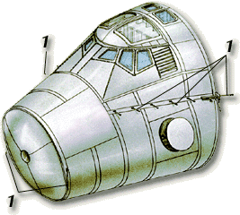
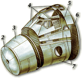
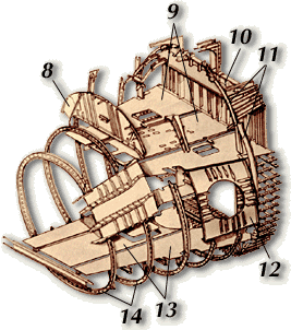
1-fixing support in the nasal part of the fuselage; 2-Front dividing wall; 3-Envelope; 4-Part of the enveloppe of the piloting section; 5-Rear dividing wall; 6-Rear of the cabin; 7-Plates of the envelope of the livable section; 8-Front cockpit dividing wall; 9-Top floor; 10-Rear dividing wall; 11-Beams of reinforcement; 12-Support of the trap door; 13-Lower floor; 14-Circular beam of reinforcement;
The cabin was conceived and built by the design bureau Myasishchev, it was then tested on the OK-GLI shuttle. The module of 5.4 m length , more than 5 m width and of 5.4 m height entirely in metal and hermetically welded, shelters the control unit of the crew, the electronic equipment of piloting and SGO equipment. The body of the cabin includes an outside envelope, six beams of reinforcements, the dividing fronts and back walls and is composed of "corrugated" panels manufactured by the milling of aluminium welded alloy plates then sets together. The structure is reinforced by beams at the place of the trap doors and port-holes of glass because of the variations of curve of surface.
The large-sized beams reinforcements are fixed on the external part (panels of the envelope) by mechanical welding or joints.
The top and lower floors are used as reinforcement as well as the dividing walls.
Caption:
1-Flight deck; 2-Mid deck; 3-Equipments deck; 4-Airlock; 5-Commander seat (PM1); 6-Pilot seat (PM2); 7-Onboard engineer seat (PM3); 8-Place for the rendez vous operator (PM4); 9-Place for the KBO PG operator (PM5); 10-Place for the PG specialist (PM6); 11-PG specialist seat (décollage- atterrissage); 12-Trapdoor; 13-Trapdoor to the life deck (normale); 14-Trapdoor to the life deck (secondary); 15-16-Airlock's trapdoor (ChKK); 17-Trapdoor to the equipment decks; 18-Upper porthole; 19-Payload bay's porthole; 20-Bunks place; 21-Stowage place n°1; 22-Stowage place n°2; 23-Stowage place ASU; 24-Pantry; 25-Stowage place n°5; 26-Stowage place n°6; 27-Stowage place n°7; 28-Stowage place n°7a; 29-Starboard equipments; 30-Port equipments; 31-Tools and furnitures for the toilet block; 32-Command module; 33-Star navigation system; 34-Equipment SU, SBM, RVV (PO16); 35-Stowage place n°17; 36-Stock of movie camera bands.
Angles of view in degrees (abscissa and ordinate) from the commander seat:

The floors and the dividing walls divide the volume of the cabin into 3 sections: the section of piloting, in which the crew settles, the livable section in which is located the computer, the trap door for accessing the cabin, as well as the possible travellers, and the section of the machines in which is located the auxiliary equipment and the various systems; the connection between the 2 levels is ensured by a trap door. On the front and rear dividing wall, there are electrical panels which make it possible to control the various equipments of the shuttle.
The entry trap door, which opens towards the interior, ensures the access to the livable section. On its lid is fixed the fast mechanism of closing made up of 10 bolts. 9 port-holes in the piloting section ensure a sufficient vision area for working on orbit and manual piloting during the re-entry in the atmosphere and the landing.
The rear dividing wall is drilled by a circular opening which makes it possible to install the equipment during the assembly, but also to put there the SHKK module or CM for the exit in space.
In the top part of the cabin the installing of an ejection system for the seats (for the pilot and the copilot) is possible.
To limit the heating and to reduce the noise level, the cabin was covered by a heat shield.
High requirements about the life-span of the elements were required, in particular because of the deformation and load transfer during all the stages of the flight. This requirement is ensured by the suspension of the cabin by a articulated levers device laid out in the zone of connection of the envelope and the front floor.