

- Documentation
- Table of contents
- AKC
- Introduction
- Airframe Creation
- Technological Problems
- Experimental plant
- Building plant
- Conf. Development
- Aerodynamic Designing
- Algorithms of control
- Guidance & control
- Stand for training
- Training center
- Horizontal flight tests
- Crew on board
- Auto Landing complex
- Structure
- Payload bay
- Metallic material
- Non metallic material
- Non metallic material
- Cabin assembly
- Thermal designing
- Thermal protection
- Heat protection
- Quartz fibre
- Computer designing
- Gas's dynamic
- Strength
- Basic direction
- Tech. preparation
- Technical diagnostics
- Methods & means
- Radio nav. support
- Information & controls
- Control of onboard equ.
- Electric power dist.
- Electromagnetic
- Antennas installation
- Auxiliary power unit
- Hydraulic system
- Cabin
- Safety
- Air transportation
- Automatic landing
- Exp. working out
- Return to space
- SPIRAL
- Analysis of concept
- Horizontal take-off
- BOR-4 & BOR-5
- MAKS multipurpose
- MAKS-D
- Thermal design
- Gas & thermal design
- Wing deflection
- Flight performance
- Maks structure
- Metal materials
- Advanced non metallic
- Information provision
- Onboard starting comp.
- Onboard control comp.
- Control organization
- Aerospace systems
- Economic investigations
- Triplane aircraft
- Technical inventions
- Scientific potential
- Triumph and tragedy
- Birds of a Feather?
- TsAGI wind tunnel
- Bibliography
| -The Mriya is destroyed. |
| -Shipping of Buran-KS to Sotchi. |
| -Antonov is no more. |
| -Buran is now a museum. |
| -New pictures of the blogger Ralph Mirebs. |
BURAN Orbital
Spaceship Airframe
Creation
Trajectories of BURAN Orbiter’s Descent and Landing
Algorithms of the Automatic Guidance and Control
Dr. Kirpisсhikov V.P.
Some results of works fulfilled by NPO MOLNIYA, NPO AP, MARS Design Bureau, NPO ENERGIYA, TsAGI, LII and other organizations, that took part in the decision of the automatic descent and landing problems for the BURAN Spaceship (Orbiter), are considered. The paper describes main difficulties in development of the Guidance and Control System. It presents accepted for the BURAN Orbiter principles of trajectory formation and review of the works on the automatic Guidance and Control algorithms for the descent in atmosphere and landing. Sequence of the trajectory legs, statistical tubes of trajectories, as well as actual trajectory of the first BURAN flight from height of 100 km up to touch to runway of the airfield are shown.
Main points
Guidance & Control System is very important component of the BURAN Orbital Spaceship. Its operation correctness, accuracy and reliability completely determined success of Orbiter’s descent to the airdrome and landing.
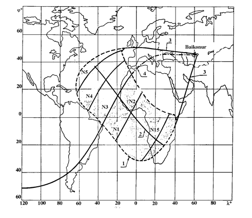
The problem of development of the Automatic Guidance & Control algorithms was very difficult. Under operational conditions the Orbiter should have a capability from any point of allowable entry area (at the 100 km altitude - Fig. 1) in time by little more than 30 minutes to land into the given aerodrome. The destination point is situated at the distance ∼ 8000 km from entry point at altitude of 100 km. At Orbiter’s descent an landing flight velocity is reducing from 28000 km/h down to zero. Orbiter’s flight and braking in atmosphere are made at presence of strict restrictions on trajectory, connected to aerodynamic heat, g-loads factor and dynamic pressure. Additional restrictions are connected to limited fuel reserve for the Reaction Control System (RCS) and Hydraulic Steering System for aerodynamic control surfaces, and also requirements of successful landing fulfillment in case of any two failures of descent and landing systems.
All this was done taking into account a broad set of disturbances:
- initial atmospheric entry conditions dispersions;
- atmosphere thermodynamic parameters deviations (density, pressure, temperature) from standard values;
- current zonal wind, gusts and atmospheric turbulence;
- measuring and information means uncertainty;
- Orbiter’s aerodynamic characteristics definition errors;
- Orbiter’s centering and mass-inertia characteristics definition errors.
All these disturbances, actually, have random character, changing not only from flight to flight, but also during the same flight. It is impossible to define the Orbiter’s descent fixed planned trajectory in atmosphere and its landing. We can only consider trajectories design tube, where with definite probability there should be an actual trajectory.
BURAN Orbiter design tubes were determined for probability P = 0,997.
BURAN Orbiter descent problem from Area of Allowable Entry Conditions (AAEC) at the altitude of 100 km to landing was solved by the Orbiter’s full (3-D) movement on three functionally different flight stages:
|
|
Figure 1. Area of allowable entry conditions (AAEC) during BURAN Orbiter first flight: |
1 - AAEC; 2 - design (aiming) line of navigation to the altitude of H = 100 km; 3 - Flight trajectories design area borders from given AAEC to Aerodrome of Baikonur; 4 - First flight descent and landing trajectory; N1, … , N15 – number of orbit circuit
- descent stage H = 100-20 km;
- pre-landing maneuvering stage H = 20-4 km;
- pre-landing approach and landing stage H = 4-0 km.
Automatic Guidance & Control algorithms at every stage, deciding their specific problems, sequentially moved BURAN Orbiter from one area of motion parameters to another that is much narrower. The final motion parameters area on pre-landing approach stage met the requirements of the Orbiter successful landing. At each flight stage the final motion parameters areas of the BURAN Orbiter were the same for all types and operation conditions, including the case of two failures in the control system. The selection of design versions was made so that there were provided certain reserves of Orbiter’s maneuverability, stability and controllability to ensure navigating into these areas.
Area of Allowable Entry Conditions (AAEC)
BURAN Orbiter’s Area of Allowable Entry Conditions (AAEC) includes a set of geographical coordinates (latitude ϕ and longitude λ), at which BURAN Orbiter’s navigating into the given parameters area with permissible disturbances is provided (when designed disturbances action). All constraints, imposed on the Orbiter’s trajectory and control parameters, are satisfied.
In order to provide safety during the orbital flight, the AAEC area should embrace as many numbers of daily orbit circuits, as it is possible. This may be reached by maximum use of BURAN Orbiter’s aerodynamic Lift-to-Drag ratio at lateral maneuvers’ fulfillment from landing orbits circuit, passing through AAEC edges.
Figure 1 shows the AAEC area and calculated range of possible trajectories of the BURAN flight in atmosphere for the case of regular landing on the runway of Baikonur and the orbit inclination to be of i = 51,64°. The agreed border of the atmosphere is adopted at the altitude of 100 km.
In the AAEC area, shown on Fig. 1, the flight first day landing orbits trajectories and designed aiming line of the BURAN Orbiter navigating to H = 100 km altitude after de-orbit are presented. Distance from this line to designed area situated on H = 20 km is about L= 8250 km. The aiming line passes practically through the middle of the AAEC area and has approximately the same reserves on designed longitudinal distance in case of its possible increase or decrease at flight up to 20 km altitude under direct (in flight direction) or opposite disturbances operation. The aiming line extreme (from the boundary) points correspond to maximum cross descent ranges, achieved at designed disturbances.
In the same figure the BURAN Orbiter’s first flight trajectory is shown. The landing orbit circuit was the third (N3) one, with cross range up to the aerodrome of landing Lc = 570 km. The atmospheric entry at H = 100 km altitude during the first flight took place under the following conditions:
- fight velocity V = 27330 km/h;
- trajectory inclination angle θ = -0,91°;
- latitude ϕ = 14,9°;
- longitude λ = 340,5°;
- distance to runway L = 8270 km.
Descent Stage H = 100 - 20 km
The main task of the Guidance system at the descent stage from 100 down to 20 km is to form the trajectory, satisfying the following demands. The trajectory does not exceed any constraints, imposed on aerodynamic heat, g-load factor, dynamic pressure and the RCS fuel reserve. The Orbiter should be navigated into the given area of trajectory parameters at the height of 20 km in landing aerodrome region that is given as follows:
- the velocity vector is directed on tangent to the Cylinder of Energy Dispersion (CED) with permissible deviation on azimuth from tangent to CED within |Δψ| ≤ 15°;
- velocity vector module is V = 520 ± 60 m/s;
- distance along a great circle arc from the Orbiter’s center of mass up to CED tangency point is Lf = 32 ± 13 km.
- control on the current state, directed to elimination of the misalignment between actual and given beforehand reference trajectory parameters;
- control on terminal state, directed to elimination of the final miss (terminal control).
There are two basic Guidance methods for the Orbiter’s descent trajectory, ensuring its navigating into the given area with required accuracy:
For BURAN Orbiter there was selected final state guidance method with the use of the prognosis by approximating formulas (analytical prognosis). The projections of aerodynamic normal force in longitudinal and lateral planes, depending on angle of attack and roll angle, are taking as control parameters at the descent trajectory. The selected method of the final state analytical prognosis does not demand large digital computations and has definite flexibility in trajectory construction, providing at the same time the prescribed level of final parameters accuracy.
As adjustable parameters of the Guidance system were received the following:
- distance (L) along a great circle, tangent to the CED, from a projection of the Orbiter’s current position on a surface of the Earth up to tangency point;
- heading angle miss Δψ that is equal to the angle between the Orbiter’s ground velocity vector and the direction to a great circle, tangent the CED.
BURAN Orbiter’s trajectory profile on the descent stage was formed by the prescribed function of longitudinal g-load nxv from a relative flying velocity V, where nxv is the Orbiter’s g-load vector projection on relative velocity vector.
The selection of longitudinal g-load nxv as parameter of trajectory profile formation was very successful. This was because on the (nxv – V) the mentioned above constraints on trajectory are easily mapped. At the same time, integrating the nxv(V) function, given by polynomials, it is possible to receive the prognosis of the final distance as the analytical formulas in any point of a descent stage. The formation of command function nxv(V) is reduced to a periodic refinement of the approximating polynomials’ coefficients from a condition of equality predictable and required flight ranges up to point of destination.
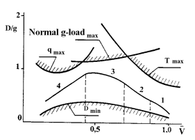
In Fig. 2 the general view of command function for longitudinal g-load nxv(V), adopted for BURAN Orbiter, where V = V/Vcirc (dimensionless relative velocity), Vcirc (circular orbit velocity), nxv = D/g, D – drag, g – acceleration of Earth gravity, is shown.
In Fig. 2 the constraints on permissible maximum values of aerodynamic heat temperature (Tmax), dynamic pressure (qmax) and normal g-load, as well as boundary of physically possible area of quasi-stationary gliding flight with zero roll angle (minimum drag Dmin) are also shown.
|
|
Figure 2. Longitudinal g-load change profile for the Orbiter’s descent: |
1, 2, 3, 4 – the descent legs’ numbers
The function nxv(V) was broken on four legs and every one was described by its polynomial. Having navigational value of distance up to an aiming point and evaluating forecasted flight range, it is possible to define on discrepancies the required ‘hitting’ profile of longitudinal g-load nxv(V) change.
The obtained command g-load relation to speed is traced during control stage by holding the definite vertical projection of aerodynamic lift-to-drag ratio (L/D)eff = (L/D)cosγ (where γ is the roll angle, L, D – aerodynamic lift and drag), that is reached by change of roll angle module. The sign of roll angle γ is selected taking into account a forecasted miss in cross-distance to be equal zero demand.
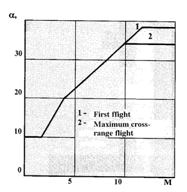
The factors (coefficients) of the nxv(V) command function depend on the angle of attack program from Mach number α = α(M). When selecting this program, the conflicting requirements, connected to a maximum lateral (cross) range capability requirements, designed thermal constraints and necessity of the descent stage’s smooth transition to the pre-landing maneuvering stage, were also taken into account. When at M > 10 velocities, aerodynamic heat conditions are limited by available Orbiter’s angles of attack to range 30° ≤ α ≤ 41°. For realization of maximum lateral (cross) maneuver the angle of attack should be close to the angle, ensuring the maximum aerodynamic lift-to-drag ratio α(L/D)max = 18…20°. The transition from the descent to the pre-landing maneuvering stage should be implemented at the given velocity vector without change in balancing on angle of attack.
As the result the program of the angle of attack, shown at Fig. 3, was selected.
|
|
Figure 3. BURAN Orbiter’s program on angle of attack |
|
|
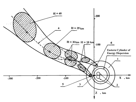
Figure 4. BURAN Orbiter first flight designed tube of trajectories with cross-sections on an altitude at the final leg of descent stage near landing aerodrome: |
1 - given area of navigating to H = 20 km for the Eastern CED; 2 - Heading Adjustment Cylinders (HAC); 3 - runway; 4 - First flight trajectory; 5,6 - design terminal areas of navigating to H = 20 km for the right and left tangency to Eastern CED
At the end of the descent stage for fulfillment given accuracy on the Orbiter’s velocity vector, the control of the angle of attack about program values in Δα = ± 3° limits was supposed.
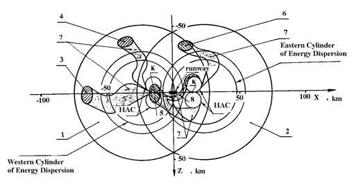
Figure 4 shows the designed tube for the BURAN Orbiter descent trajectory. The area, when BURAN is approaching the aerodrome in its first flight and guiding to the East CED (Cylinder of Energy Dispersion) taking into account all adopted spectrum of disturbances and constraints.
The algorithm of lateral trajectory control executes guidance on one of two tangents to CED. Therefore narrowed trajectories tube at approach to the aerodrome at 35 km altitude is disjointed on two.
The upper trajectories tube integrates realizations with guidance on the left (from flight direction) tangent line to CED, and the lower one - realizations with guidance on the right tangent line. The probability of the Orbiter’s navigating (to the altitude of H = 20 km) into the left terminal area was P ≈ 0,3 and P ≈ 0,7 into the right area.
|
|
Figure 5. Areas of navigating to the altitude of H = 20 km and designed trajectories tubes at pre-landing maneuvering for the first flight of BURAN: |
HAC - Heading Adjustment Cylinder; K - ‘key point’ (altitude of 4 km), when pre-landing maneuvering finished and stage of approach started; 1,2 - given rings of areas at H = 20 km for navigating to the Western and Eastern CED; 3,4 - designed areas for the 1-st flight of BURAN at navigating to the Western CED; 5,6 - designed areas for the 1-st flight of BURAN at navigating to the Eastern CED; 7 - designed trajectory tubes for the 1-st flight of BURAN; 8 - horizontal projection of trajectory for the 1-st flight of BURAN
Possible areas’ variety form rings around the Western and Eastern CED.
Pre-Landing Maneuvering Stage H = 20-4 km
The main task for the Guidance & Control algorithms at pre-landing maneuvering stage (PM) is to navigate the Orbiter from final area of the descent stage (at the altitude of H = 20 km) into a zone of stable work of landing radio means in vicinity of so-called Key Point. This point is located at the altitude of H = 4 km above runway centerline on a distance of approximately 14,5 km from center of runway. At this leg dispersion of excessive energy is done.
The problem of excessive energy dispersion can be generally solved by three methods:
- by change of trajectory extent with the help of turns for the coordination of flying vehicle current energy with range up to the designed point;
- by change of dynamic pressure;
- by change of Lift-to-Drag ratio.
A combined method was selected for BURAN. The basis was the change of trajectory extent in a combination with programmed change in the levels of Lift-to-Drag ratio and dynamic pressure. At this method the change of a path length was made by spiral turns with simultaneous stabilization of programmed values of dynamic pressure as a function from flight altitude q(H) and air brake programmed angles deviation as a function from a Mach number δab(M) (down to the point of M = 0,8). The maximum programmed dynamic pressure function q(H) should be realized at following wind (acting in flight direction) to provide intensive dispersion of energy. The minimum programmed dynamic pressure function q(H) is characteristic for flight at maximum L/D ratio when headwind.
At the start of pre-landing maneuvering stage in accordance to a level of Orbiter’s mechanical energy and state vector the Guidance system forms a 3-D reference trajectory, connecting the Orbiter’s initial position at H = 20 km altitude with Key Point. The projection of the reference trajectory to a horizontal plane generally consists of five stages: a spiral of turn-away, spiral of corrective turn, tangent to the Heading Adjustment Cylinder (HAC), arc of HAC circle, finishing straight line to the Key Point. When reference trajectory forming for nominal programmed function q(H) by ‘spiral’, ‘straight line’, ‘arc of a circle’ elements interface, four possible versions of trajectories in a horizontal plane without turn-away are determined.
The programmed function relation of the Orbiter’s flight altitude from the remaining distance to the Key Point is determined for each trajectory. The selection of a reference trajectory from four possible ones is done by sequential comparison of required and available Orbiter’s energy. As reference one the trajectory at which the misalignment in energy does not exceed permissible value. A trajectory with the energy miss, not exceeding allowable value, is accepted as the reference (nominal) trajectory.
The turn-away is performed, if the best trajectory without turn-away has insufficient extent for the Orbiter current energy state or in a case of inadmissible large cross-section of HAC by a spiral.
The value of mechanical energy is controlled in flight of Orbiter. Under unfavorable conditions (current cross deflection from reference trajectory exceeds permissible value), and also in points of turns on a roll (turn-away spiral end, corrective turn spiral end) the reference trajectory is redefined.
When reference trajectory forming, the constraints on hinged moments of control drives, dynamic pressure, angles of attack and roll and g-loads, as well as requirement of a minimum change in balancing, are taken into account when transition through transonic area.
The Guidance & Control algorithms navigates the Orbiter into the Key Point (H = 4 km) area by stabilization around calculated 3-D reference trajectory at M > 0,8 leg. Navigating at M < 0,8 leg is done by stabilization around reference ‘track’ in horizontal plane and terminal guidance to the Key Point in vertical plane. Thus the parameters of flight in Key Point should be inside the following ranges:
- on the altitude H = 4000 ± 500 m;
- on cross deflection |Z| < 500 m;
- on speed V = 170 ± 20 m/s;
- on the angle of trajectory inclination to horizontal plane θ = - 17± 6°;
- on heading angle |Δψ| < 10°.
At Fig. 5 the designed tubes of BURAN Orbiter’s trajectories at pre-landing maneuvering stage, defined for conditions of the first flight, are shown. The BURAN trajectory in the first flight is also at Fig. 5.
As it was already indicated, during the first flight of BURAN Orbiter the navigating to the right tangent line of the Eastern CED with 5 area at H = 20 km altitude (Fig. 4, 5) was done. As the statistical calculations have shown, there are two tubes of possible trajectories from this area into the Key Point (Fig. 5). One tube goes around of Southern HAC, and the other one around of Northern HAC. The Orbiter hit probability in a southern tube was evaluated by value P = 0,97, and in northern by P = 0,03. Nevertheless, in the first flight at H = 20 km altitude forming conditions were created of a reference trajectory around of northern HAC. BURAN Orbiter first flight was done on this trajectory.
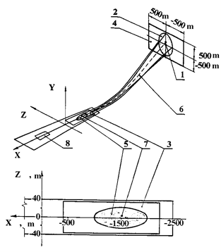
Designed area of BURAN Orbiter navigating into the Key Point in conditions of the first flight and its actual position in this area are shown in Fig. 6.
Approach and Landing Stage H = 4-0 km
The main problem for the approach and landing stage is the exact turn of velocity vector on landing heading and the Orbiter’s steering along the reference trajectory into the given touching point on the runway with accuracy, guaranteeing safety and comfort of the touchdown.
At this stage the Orbiter’s Guidance task is to follow along given reference trajectory and stabilization of programmed function for the instrumental speed.
Low aerodynamic Lift-to-Drag ratio and the restricted mechanical energy capabilities at flight speed regulation have predetermined the use of the two-glide-path approach scheme with a leg of smooth interface between them.
|
|
Figure 6. Designed trajectories tube for BURAN Orbiter 1-st flight at approach and landing stage: |
1 - Key Point H = 4 km; 2 - designed area of navigating to H = 4 km; 3 - given area of runway contact; 4 - given area of initial conditions; 5 - designed area runway contact in the first flight; 6 - BURAN trajectory in the first flight; 7 - runway touching point in the first flight; 8 - the area of Orbiter’s stop on runway
The value of inclination angle of an abrupt glide path is chosen (depending on the Orbiter’s weight) in the range of θ = -17 ... -23° from equilibrium glide condition with constant instrumental speed Vinstr = 520 km/h with an average angle of the air brake deflection of δab = 55°. At this stage the errors of the Orbiter’s guidance in the Key Point are compensated.
From an altitude of 400 m the Orbiter equalization from an abrupt glide path on a flat one with trajectory inclination angle of θ = - 2° is made.
The programmed interface leg, being of θ = - 10° trajectory inclination, for junction of abrupt and flat glide paths is intended for lowering the maximum of normal g-load ny, appearing at the first equalization. The flight on the first equalization stage and on the flat glide path is done with programmed decrease of instrumental speed depending on the remaining distance.
The duration of the flat glide path should be sufficient for stabilization of flight parameters before final equalization and landing. The final equalization begins after transiting the front edge of runway at H = 20 m altitude. During this stage, depending on conditions requirements at H = 20 m and operational wind disturbances, an exponential trajectory with monotonically increasing pitch angle is formed in order to provide the fulfillment of given requirements at the moment of runway touchdown.
The parameters of motion in the given touching point should be in the following ranges:
- longitudinal distance from runway center in landing coordinate system X = - 2200... - 400 m at a nominal value of - 1500 m;
- deflection from a runway center line |Zlcs| ≤ 38 m;
- ground speed at contact V ≤ 360 km/ h;
- vertical velocity at contact |Vy| ≤ 3 m/s.
At Fig. 6 the designed tube of BURAN Orbiter trajectories at the approach stage and landing and designed area of runway contact, defined for conditions of the first flight, are shown; the actual trajectory of the first flight is also schematically shown. Despite of the strong head quartering gusty wind with speed W = 15…18 m/s, the conditions at contact were practically ideal ones:
- X = - 1515 m (ΔX = - 15 m);
- Z = 5,8 m;
- V = 263 km/h;
- Vy = - 0,3 m/s.
Stabilization System
When developing stabilization system, the selection of rather small number of designed cases was very important, on the basis of which it was possible to conduct the basic volume of researches and calculations.
To the main designed cases were included several the worst ones on stability and controllability of combinations of the Orbiter’s aerodynamic characteristics dispersions because of possible errors of their definition:
- Orbiter’s minimum stability and maximum efficiency of control devices;
- the worst controllability by elevons in a mode of ailerons;
- worst balancing ability by elevons;
- the worst controllability by elevons and rudder;
- other design cases.
In every case the possible failures and maximum deviations (by the module) of the following characteristics were additionally taken into account:
- unfavorable dispersions in longitudinal and cross-sectional center-of-gravity positions and moments of inertia because of possible errors of their definition;
- unfavorable on the sign aerodynamic hinge moments spreads;
- unfavorable combinations of characteristics dispersions of RCS jet engines interference;
- the worst (the best) parameters of control systems and RCS (in the boundaries of the tolerances);
- designed gusts of the unfavorable sign arising in the most unfavorable points of time;
- unfavorable on the sign of the angle of attack and slip angle measurement errors;
- two failures in a hydraulic-circuit system of control drives or RCS engines.
There is probable the occurrence of flight legs with one or other sign of Orbiter’s reaction on a deviation of the control surfaces or even the loss of controllability could take place or did not take place, depending only on a combination of spreads of errors in the aerodynamic characteristics. This is due to the presence of many parameters, non-linearity and large enough uncertainty of the Orbiter’s aerodynamic characteristics in a combination with variety of flight trajectories and broad range of angle of attack change. This circumstance to a great extent has stipulated the complexity of a task of stabilization algorithms synthesis. All known methods of synthesis (frequency characteristics, root locus, phase plane etc.) were suitable for the narrow problem solution only, but did not get a solution for the problem as a whole. Therefore main method became the method of stability regions construction and quality.
This method grounded on a numerical integration of a closed-loop equations system, including linear model of the object with ‘frozen’ factors and full non-linear models of control algorithms and actuators.
In all cases the transients, called by control commands, or by gust, are analyzed.
In order to enter permissible area (the satisfactory process), system control parameters should fulfill a number of criteria, different in each particular case. Thus presence of an examined point inside obtained method guarantees not only stability, but also required quality of transients. The complexity of the given method consists of a large number of designed cases, causes the necessity of the generalized area of interception of all separate areas. When such interception did not exist, the system of stabilization was modified.
The final working out for stabilization system algorithms was conducted at flight dynamics identification with the help of a large simulating complex, containing BURAN Orbiter full model and its control devices, model of atmospheric disturbances and full models of navigation systems, guidance and stabilization systems. It is necessary to mention that selected by the mentioned method structure and set-up of stabilization system adjusting by results of full simulation practically did not have to be corrected.
Conclusions
1. The first flight of the BURAN Orbiter has confirmed efficiency of designed principles of trajectory formation and automatic guidance algorithms at descent and landing stages in atmosphere. The automatic Guidance & Control system ensured BURAN Orbiter motion inside the normal trajectories tube on all flight stages up to touchdown, that was made with high accuracy, despite of a strong gusty wind.
2. Developed for the BURAN Orbiter designing and working out of the automatic control system techniques can be used for the solution of similar problems at development of the advanced spaceships of other types or winged stages of rocket complexes.
Epilogue
Both landing and descent problem of the BURAN Orbiter solving and creation of automatic Guidance & Control algorithms is the result of collective work of hundreds highly qualified scientists and engineers of different specialties from many enterprises and organizations.
The main activity on creation of automatic Guidance & Control algorithms for descent stage was made in NPO AP, headquarters plant on the Orbiter control system as a whole, where the qualified collective solved the problem. The head were Dr. Hitrik M.S and Lebedev V.S. The ideologists and conducting experts in collective were: Dr. Hazan. M.A., Baskakov I.M., Litvinov U.U., Beketov V.L., Petrosyan L.L., Nikonorov V.N., Malkin V.N., Akimov V.I.
The main activity on creation of automatic algorithms for the pre-landing maneuvering, landing approach and landing stages was made at the MOKB MARS Design Bureau. The head designers were Dr. Sirov A.S. and Bonk R.I. Lipkin A.L., Andreev V.P., Dubinkin I.M., Kovalsky V.S., Rudenko T.N., Mrs. Muravleva G.A. etc played leading part in the project.
The large activity on the solution of descent and landing problems and creation of automatic algorithms was conducted in NPO MOLNIYA, headquarters plant on the Orbiter’s airframe and responsible for flight of the Orbiter in atmosphere. In these questions solution of the following team from NPO MOLNIYA took part:
At the head - Dr. Samsonov E.A and Mr. Naboischikov G.F., the leading specialists were also Mrs. Korobova T.N., Mr. Lisenko A.P., Dr. Shiryaev I.N., Fedorov V.E., Altshuler A.S., Mr. Gorbunov N.I., Dr. Dudar E.N., Mr. Pimenov V.G., Sergeev I.V., Beskorovainy Mrs. V.V., Babaeva Z.V., Dr. Volodin V.D., Mrs. Kirichenko Z.S., Sherbakov S.N., Shilova G.A., Baranov U.A.
The very important activity in the solution of general problems of descent and landing and in coordination of activity different enterprises was conducted in NPO ENERGIYA, headquarters plant on a complex as a whole, where the collective under a management of Dr. Timchenko V.A. worked. In this collective a conducting role played: Dr. Ovsyannikov V.A., Sotnikov B.I., Visokanov V.A., Lebedev G.V., Patsiora A.I., Grigoriev L.S.
It is necessary also to mention the large creative contribution to research of descent landing and creation of motion automatic control algorithms. That contribution was made by Prof. Yaroshevsky V.A., Dr. Kobzev V.I. and Bobilev A.V. (TsAGI); Dr. Kalugin A.P. and Krasnov B.M (LII); Mrs. Kerber O.B. (MIEA); Prof. Sikharulidze U.G. (IPM); Dr. Lobanov V.S. (TsNIIMASH).
The author highly evaluates creative potential of these people, their service to business and he is happy that for many years he lived and worked among them.