

- Documentation
- Table of contents
- AKC
- Introduction
- Airframe Creation
- Technological Problems
- Experimental plant
- Building plant
- Conf. Development
- Aerodynamic Designing
- Algorithms of control
- Guidance & control
- Stand for training
- Training center
- Horizontal flight tests
- Crew on board
- Auto Landing complex
- Structure
- Payload bay
- Metallic material
- Non metallic material
- Non metallic material
- Cabin assembly
- Thermal designing
- Thermal protection
- Heat protection
- Quartz fibre
- Computer designing
- Gas's dynamic
- Strength
- Basic direction
- Tech. preparation
- Technical diagnostics
- Methods & means
- Radio nav. support
- Information & controls
- Control of onboard equ.
- Electric power dist.
- Electromagnetic
- Antennas installation
- Auxiliary power unit
- Hydraulic system
- Cabin
- Safety
- Air transportation
- Automatic landing
- Exp. working out
- Return to space
- SPIRAL
- Analysis of concept
- Horizontal take-off
- BOR-4 & BOR-5
- MAKS multipurpose
- MAKS-D
- Thermal design
- Gas & thermal design
- Wing deflection
- Flight performance
- Maks structure
- Metal materials
- Advanced non metallic
- Information provision
- Onboard starting comp.
- Onboard control comp.
- Control organization
- Aerospace systems
- Economic investigations
- Triplane aircraft
- Technical inventions
- Scientific potential
- Triumph and tragedy
- Birds of a Feather?
- TsAGI wind tunnel
- Bibliography
| -The Mriya is destroyed. |
| -Shipping of Buran-KS to Sotchi. |
| -Antonov is no more. |
| -Buran is now a museum. |
| -New pictures of the blogger Ralph Mirebs. |
BURAN Orbital
Spaceship Airframe
Creation
Methods and Means of Air-Tightness Control of BURAN Orbiter Construction
Chernousov V.N.
The principal methods of BURAN Orbiter hydraulic and gas units and systems air-tightness control, including isobaric, acoustic, compensating-differential, mass-spectrometric and of radioactive indicators, and also the means of their implementation are surveyed. The possible fields of these methods and means implementation in the national economy are shown.
The air-tightness control is one of the kinds of a non-destructive testing, which specific feature is detection of small and ultra small through penetrating leakage. Such control took a considerable place in production of BURAN Orbiter.
Methods of air-tightness control are based on registration of substances permeating through leakage, and allow revealing through defects, which cannot be detected by other methods.
In BURAN Orbiter construction, the elements essentially differing in overall dimensions, materials, degree of manufacturing completeness, operation conditions, permissible norms of leakage were checked up for air-tightness. This circumstance has determined the choice of air-tightness control method of BURAN Orbiter construction.
The main methods of BURAN Orbiter construction air-tightness control are: isobaric, acoustic, compensating-differential, mass-spectrometric and method of radioactive indicators.
Isobaric Method
The method is used for quantitative definition of aggregated mass of the air inflow or outflow through detachable and permanent joints, panels’ splices, fasteners and seals of airframe.
When the isobaric method is used as the control of air-tightness the constant pressure or rarefaction is sustained in the airframe. The flow rate of pressurized or evacuated air is determined numerically by pressure differential in the pneumatic system. This differential is estimated on the convergent device at the steadied pressure in the airframe in view of temperature of air.
Permissible aggregate non-tightness of BURAN Orbiter airframe at standard conditions (В0 = 760 mm Hg, Т0 = 288oК), and at rarefaction inside fuselage is determined by pressure differential
ΔР = Рstruc − В0, (1)
where Рstruc pressure in airframe.
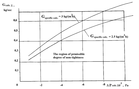
The dependence of reduced aggregate leakage on pressure differential is shown in Figure 1.
Calculation of air flow and pressure differential was made under the formulas:
Gcalc. = Gmeasur. 760/В0 √( Т0 /288 ), (2)
ΔРcalc. = 760ΔРmeasur. / В0. (3)
When the pressure differential is constant, air consumption G is a measure of leakage.
At manufacturing stage of separate units of BURAN Orbiter construction (wing, vertical tail, etc.) the admitted norm of non-tightness is 2.5 kg/(m3h), which at a volume of airframe equal to 850 m3 gave Gcalc. < 2550 kg/h.
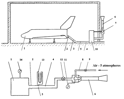
To determine an aggregate non-tightness of BURAN Orbiter airframe construction a special stand was created (Figure 2). For ejection of air, compressed air of factory mainline was used. The ejector was calculated for creating rarefaction up to Р = - 9.8×10³ Pa in airframe at permissible leak rate. In the pipeline of the stand, the Venturi type nozzle is located, which serves for air flow rate determining. Mass flow rate was determined under the formula
G = α ε (πd2/4) √( 2ΔРnozzle ρ ), (4)
where α - flow rate coefficient, ε - air expansion ratio, d - diameter of Venturi type nozzle, ΔРnozzle - pressure differential on nozzle, ρ - air density.
|
|
Figure 1. Dependence of aggregate degree of airframe leakage on pressure differential |
The working conditions of airframe body of the spacecraft are characterized both by positive and negative pressure differential in it stipulated by the flight profile. The pressurization system and cooling valves make pressure regulation of the airframe body. The availability of information about airframe’s aggregate non-tightness is extremely important in this connection, which registration allows to increase the control accuracy of pressure in airframe body. At the same time, the value of air flow rate defined by an aggregate leakage through conjunctions of the airframe, is necessary for calculation of power characteristics of production equipment. This equipment ensures the condition of flight by the pressure in the airframe body in terrestrial conditions for a long time required for detection of a local non-tightness of doors, gates and hatches covers seals. The isobaric method has been developed by engineers: Mr. Drozdov V.D. (NIAT), Deshkin V.B., Stesnyagin A.G., Rozanov I.G. (NPO MOLNIYA). It was first applied for detection of the aggregate non-tightness in BURAN Orbiter airframe. This method can be used for the control of air-tightness of wide-body airplanes.
Acoustic Method
Taking into account the design features of BURAN Orbiter, for the control of air-tightness of airframe seals, the acoustic method is the most acceptable. The method does not require application of special trial (indicator) substances and provides an opportunity of remote monitoring.
The acoustic method of leakage detection is based on reception and processing of ultrasonic oscillations generated by a gas jet flowing out through a leak, filtration of the obtained signal with the purpose of exclusion of outside noises and its subsequent conversion for indication of the leakage.
The technology of air-tightness control of all types of doors, gates and hatches covers sealing of BURAN Orbiter airframe was based on an acoustic method with application of a leak detector of Ultrasonic Detector type made by Electronic Detectors firm (Belgium). For usage of the leak detector NIAT, together with NPO MOLNIYA developed different simulators of leakage’. With the help of these simulators, the position of the sensitivity regulator of the device was determined.
|
|
Figure 2. Scheme of experimental stand |
1 - vehicle, 2 - connector, 3,4 - pipeline, 5 - Venturi type nozzle, 6 - chamber of displacement, 7 - nozzle, 8 – pipe of high pressure, 9 - reduction gearbox, 10 - console, 11,14 - pressure gauge, 12 – gate valve, 13 – piezo-meter
At set-up of the leak detector, besides the useful signal from the simulator of leakage, the ultrasonic component of ambient noise was fixed. Therefore for detection of a local leakage of airframe construction under the same conditions, at which the set-up was conducted, undistorted by interference information on value of leakage was received.
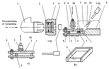
In Figure 3 the leakage simulators are shown. By these the defects were simulated in metal constructions (simulator of the 1st type), for doors, gates and hatches covers joints seals (simulator of the 2nd type), for seals of mobile joints of elevon with wing, flap with fuselage, etc. (simulator of the 3rd type).
The airflow rate through control leak of simulators was adjusted by selection of copper washers of different diameters, change of contraction effort and selection of felt seals thickness. The airflow through leakage simulators was formed by pressure differential on their seals, for which purpose the closed volume on the one side of construction was either evacuated or pressurized.
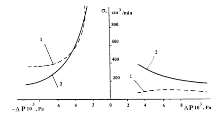
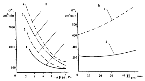
The researches showed that the acoustic method sensitivity at evacuation and pressurization of the inspected volume was various and maximum at positive pressure differential (airflow through the leakage was directed to the leak detector). Besides, the power of radiated ultrasonic signal depended on ΔР (Figure 4). The influence of design features of joints of BURAN Orbiter construction is shown in Figure 5.
From Figure 4 and 5 it is visible that at higher pressure the sensitivity of the acoustic method for different leakage simulators and different inspected joints is practically the same.
For operating pressure differential for leakage (7.8…9.8)×103 Pa, the intensity of ultrasonic signal at passing through a felt insert is decreased by 3…4 times (Figure 5a and curve 3).
|
|
Figure 3. Leakage simulators for study of ultrasonic leak detector (USL) sensitivity |
a - simulator of the 1st type: 1 - t-junction, 2 - rubber gasket, 3 - washer of copper foil with hole, 4 - nut; b - simulator of the 2nd type: 1 - fragment of a profile of rubber seal, formed together with gasket, 2 - lower slice, 3 - stepwise cut-out, 4 - adjusting bolts, 5 - upper slice, 6 - pipe connection, 7 - TPS tiles simulators, 8 - U20 pressurizer, 9 - felt insert or metal step, 10 - simulator of adjacent surface, 11 - bundle, 12 – “brush”; c - simulator of the 3rd type: 1 – felt, bundle or brush seal, 2 - upper slice, 3 - pipe connection, 4 - bolts, 5 - gasket, 6 - lower slice
|
|
Figure 4. Sensitivity threshold of ultrasonic leak detector of Ultrasonic Detector type for simulator of leakage |
1 - simulator of the 1st type, 2 - simulator of the 2nd type
|
|
Figure 5. Dependence of Ultrasonic Detector USL sensitivity on design factors |
а - on presence of a Felt Insert (FI) and TPS: 1 - simulator of leakage without FI, without TPS, 2 - without FI, with TPS, 3 - without TPS, with FI, 4 - with FI, with TPS: (thickness of TPS HТЗП = 30 mm); b - on thickness of TPS (HTPS): 1 - pressure differential on the simulator of leakage ΔР = 4.9×10³ Pa, 2 - ΔР = 9.81×10³ Pa
The increase of TPS thickness from 0 to 500 mm reduces the signal intensity approximately by 2 times (Figure 5b, curve 2). Because of the pressure differential, the influence of felt insert and TPS on the efficiency of acoustic leak detector decreases.
Bundle and brush thermal seals, fillings in inter-tile space of TPS at the joints of doors/gates and hatches covers completely damp the ultrasonic signal from the leakage, and for the control of air-tightness through a slot in TPS they should be removed.
It is established that when there is a gap between the door edging and mating part of construction of 0.5 mm, the ultrasonic signal reaches the leak detector practically without loss.
By results of researches, the permissible norms of local air-tightness for joints of doors/gates and hatches covers of BURAN Orbiter airframe were critically revised. The value of pressure differential was increased. The checks by acoustic method of airfoils mobile joints felt seals were cancelled, the manufacturing process of air-tightness control of doors/gates and hatches covers joints by acoustic method with application of leak detector of Ultrasonic Detector type was developed and implemented. This control technology for local non-tightness degree of the airframe using different simulators of leakage has allowed not only to reveal the defect location, but also to evaluate it quantitatively.
The acoustic leak detector sensitivity is determined by the intensity and frequency band of a gas jet flowing out through the leak, and such performances of a receiving device, as the range of received frequencies and level of self-noises within the limits of this range.
The noise level for leakage in cross-section of 0.01 mm (at a pressure differential of Р = 9.8×10³…1.96×10⁴ Pa) makes 15…20 dB within the limits of an octave with medium frequency of 63 kHz. This allows to detect such a leak by standard ultrasonic leak detectors of foreign firms (Helling, Germany, АЕТ LD180 model, 8900А model of Dawe and Ultrasonic Detectors firms, Belgium), which have usually the bandwidth of 6…10 kHz within the limits of range of 35…45 kHz.
|
|
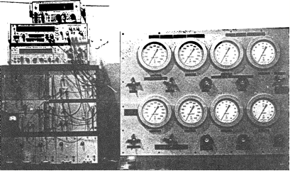
Figure 6. General view of automated system of the aggregate non-tightness for pneumatics units and systems detection by compensating-differential method |
At a narrow slot, which is characteristic for defective seal, the high-frequency signal is radiated. In this case, the receiver of ultrasonic signals can be the adequate receiving device ensuring a signal registration with frequencies over 100 kHz and with high threshold sensitivity. The sensitivity can be increased, if a two-element receiver is applied and a method of aperture synthesis used: scanning along the line defined by the outlines of seal, registration of an interference picture and computer processing of the signal. In this case the receiver should be connected to the device of signal processing on the basis of a universal computer or a special processor, which software can be designed on the basis of the known algorithms.
It is possible to obtain about the same effect while applying a correlation processing of single receiver signal using the computer synthesized signal by method of so-called ‘matched power filtration’. The additional effect can be obtained, if the receiving ultrasonic converter is structurally combined with a thermal-anemometer measuring the rate of gas flow from the leakage. Calibration of the receiving channel according to flow rate and detection of defect location is possible in this case. To increase the noise resistance of such receiver, the correlation processing is expedient.
The positive outcome can be expected, if the correlation between the output signal of thermal-anemometer and the bending of the acoustic signal is measured.
The acoustic method, in which development Mr.: Drozdov V.D. (NIAT), Deshkin V.B., Stesnyagin A.G., Mitrofanov V.V. (NPO MOLNIYA) participated, was first applied for the leakage control of BURAN Orbiter airframe seals.
This method can be used for local non-tightness detection in airframe seals of airplanes of different purpose.
Compensating-Differential Method
The control of air-tightness by a compensating-differential method stipulates the measurement of absolute values and increments of thermodynamic parameters determining the state of operating gas.
In the presence of both free and forced convection in the cockpit, heat interchange with environment takes place alongside with the leakage of gas mass through the open defects.
|
|
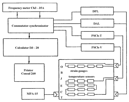
Figure 7. Scheme of aggregate non-tightness for pneumatics units and systems detection by compensating -differential method |
In linear approximation, the pressure variation ΔР in the cockpit is determined by equation
ΔР = ΔРY + ΔРT + ΔРV + ΔРC, (5)
where ΔРY - pressure variation due to leakage of gas from the cockpit (cabin);
ΔРT - pressure variation due to change of mean temperature of the medium;
ΔРV - pressure variation due to change of the cockpit volume;
ΔРC - pressure variation due to change of gas composition of the working medium.
The temperature variation in the inspected cabin is stipulated by heat interchange with environment, as well as the operation of internal heat sources. The change of volume can be induced by the change of pressure differential, which acts on the shell of the cockpit, and its temperature deformation.
As the influence of ΔРY and ΔРC on the gas absolute pressure in the cockpit (cabin) Р is negligibly small, the algorithm of detection of aggregate leakage from the cockpit looks like
Y = V / t ( ΔР − P ΔT / T ), (6)
where V - free volume of a cockpit (cabin);
ΔТ - change of mean temperature;
Т - mean temperature;
t - time of inspection.
The specific feature of the cockpit (cabin) is the presence of a non-stationary temperature field in its gas medium. Therefore, the air-tightness control of thermodynamic parameters requires the development of a method and algorithm of averaging the field of temperatures. The requirements to error of sensors of thermodynamic parameters are determined at the set measurement accuracy of leakage for determining the error of leakage according to the algorithm.
|
|
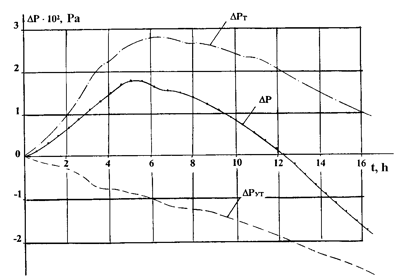
Figure 8. Results of aggregate non-tightness detection in BURAN cockpit (cabin) by compensating-differential method |
A differential pressure transducer makes the basis of the monitoring system of air-tightness with a temperature-controlled cavity, which is detaching from the gas medium of cockpit at the initial moment and in which the initial pressure is ‘stored’. The pressure difference in cavities measured with the help of differential pressure transducer at the final moment of observation is proportional to the pressure variation in the cockpit. The experimental researches of air-tightness system monitoring were executed on a physical analog and nominal cockpit according to the designed technique.
The usage of the differential pressure transducer with temperature-controlled storing cavity enables to measure the pressure drop with the required sensitivity, but does not provide a complete solution of the task without measurement of mean temperature and volume change. With the purpose of development of effective algorithm of mean temperature registration, the researches of temperature field structure in the cockpit were performed.
The computer analysis of experimental data was accomplished with the use of a package of statistical programs.
Average values, standard deviations and their changes were obtained and studied during experiment, the correlation analysis of the temperature field was carried out, the regressive model was built and analyzed.
The obtained temperature field model allowed determination the average temperature of gas medium Т aver.:
Т aver. = Σ Сi Тi , (7)
 (8) (8)
|
Тi - temperature of the i-th sensor,
α - parameter of averaging,
Сi - coefficient corresponding to a weighted function such as Gauss band, which is used at harmonic analysis of processes.
The developed estimation of Тaver. makes it possible to reduce the error of mean temperature registration as compared to the mean arithmetic at the same number of sensors.
The offered algorithms of sensors usage have allowed to develop the automated monitoring system of air-tightness of cockpits for thermodynamic parameters (Figure 6, 7).
The sensors’ part of the system contains differential pressure transducer, temperature sensor, sensor of absolute pressure and deformation sensor. The signals from the sensors’ part of the system are sent to the unit of processing, which simultaneously performs control functions. The estimation of leakage value calculated in the unit of processing according to the algorithm, moves to the display unit to diagram board or paper tape.
A difference sensor of a capacitance type is used for measurement of pressure variation in the complex. The double thermostatic control of gas in a storing cavity is applied in the sensor. The range is ± 1.5×10³ Pa, the error is ± 2.7 Pa.
Temperature measurement is made by the thermal-resistor sensors of IS545 type. The sensors are installed in the cockpit. Thermistors are connected to a converter. The frequency of an output signal of the converter is proportional to the change of resistance of the thermistor and, therefore, to the temperature variation of the medium. The measuring error of temperature variations is +5 x 10⁻³ K.
Converter with a quartz sensitive element is used as an absolute pressure gage. The principle of operation of the sensor is based on dependence of a resonance frequency of a quartz slice on the value of the applied effort. The range of the sensor is 0…2×10⁶ Pa, the error is ± 2×10² Pa.
The deformation measurement of the vehicle’s shell is made by strain-gauge indicators of 2PKB 200 type, installed on the shell. The unit, identical to the one used for signal conversion by thermistors, executes the conversion of resistance change into frequency.
The signals from the sensors are sent to converter in a frequent form, and after the output of the latter – to the digital recorder.
The parameters were measured multiply at small intervals and averaged for smoothing of a random component of the error.
After a set-off stop, the sensors’ survey was repeated, and the value of leakage was evaluated by the results of measurements. The set of factors approximating the sensors’ performances obtained by the results of tests was used at calculation.
The outcomes of experimental studies of the automated detection system of cockpit aggregate non-tightness are displayed in Figure 8. The developed technique allows to detect an aggregate non-tightness of cockpit with the minimum rate of pressure variation of 1.33× 10⁻¹ Pa/s.
The designed automated monitoring system of a degree of an aggregate non-tightness of BURAN Orbiter cockpits can be used for the control of pneumatic units and systems of flying vehicles of different purpose.
Engineers Mr.: Drozdov V.D. (NIAT), Maleiko L.V., V.A.Maglysh, Shabanov A.P. (TsNII RTK), Deshkin V.B., Stesnyagin A.G. (NPO MOLNIYA) participated in creation of the automated control system.
The solution of problems of metrology support and technologies of aggregate non-tightness of pneumatic units and systems detection by compensating-differential method will promote the increase of the control authenticity.
Mass-Spectrometric Method
The mass-spectrometric method is most widely used for the control of air-tightness of pneumatic-hydraulic units and systems of space flying vehicle.
The helium leak detectors substantially determine the quality of technology of the mass-spectrometry control of hydraulic and gas units and systems. The analysis of outcomes of theoretical and experimental works in this direction allows understanding the principal tendencies of its development.
Many domestic and foreign firms produce mass-spectrometric leak detectors made according to different principal schemes, in different designs and equipped with different gadgets.
The comparative estimation of air-tightness control methods displays a wide range of opportunities and advantages of mass-spectrometric method in comparison with others, which allows it to remain one of the main tools of the highly sensitive air-tightness control.
Within the framework of BURAN Orbiter creation program, the technologies of control of high-tight bulky cockpits by mass-spectrometric method, by ways of ‘accumulation at ambient pressure’ and evacuation with application of TVU1000 thermal-vacuum chamber. The considerable contribution to development of these technologies was introduced by engineers Mr.: Drozdov V.D. (NIAT), Lyutikov K.P., Gorbenko Yu.M. (EMZ), Deshkin V.B., Sokolov A.P. (NPO MOLNIYA).
The control of cockpit air-tightness within the structure of airframe due to a number of its design features (configuration, presence of thermal insulation, overall dimensions, etc.) was an integrated technical task, which complexity was determined also by the high requirements to air-tightness.
The analysis of test methods on air-tightness has shown that the required sensitivity of control can be ensured by way of ‘accumulation at ambient pressure’. The specificity of the testing scheme of cockpits by way of ‘accumulation at ambient pressure’ was in using the nose part of fuselage (NPF) of airframe as the chamber of accumulation, which had a disconnected system of circulation working for pumping through NPF.
Such a scheme of tests allows, after the conditioning under pressure, to create the increased density in the zones of non-tightness of cockpit and to register these zones by occurrence of maxims on the curve of density change. The values of maxims and intensity of density decay characterize the leak rate of the cockpit.
Processes of trial gas carry happening in the accumulation chamber are stipulated, on the one hand, by the air exchange between the volume of the chamber of accumulation and test space. On the other hand, by adsorption of trial gas by structural materials of the cockpit and the chambers of accumulation, result in decrease of trial gas density in the chamber. In the absence of the trial gas flow in the chamber of accumulation, these processes with the initial conditions C(0) = C0 are described by differential equation
dC/dt = − C/T1 − C/T2 = − C/T0 . (9)
At that 1/T0 = 1/T1 + 1/T2 , (10)
where Т1 is time describing density decreasing of trial gas in the chamber of accumulation under action of air exchange between the chamber of accumulation and test space;
T2 is time describing decreasing of trial gas density in the chamber of accumulation under action of adsorption of trial gas by structural materials of the cockpit and chamber of accumulation;
Т0 is time describing decreasing of trial gas density in the chamber of accumulation under aggregate action of air exchange between the chamber of accumulation and test space, and also adsorption of trial gas by structural materials of the cockpit and chamber of accumulation. Solution of equation (9) at C(0) = С0 is an exponential correlation.
If the flow of trial gas incomes into the chamber of accumulation, then as a result of the above-stated processes, the density of trial gas in the chamber of accumulation grows non-linearly:
С(t) = С0 exp( − t/Т0) +
+ (РAV) F Т0 [1 − exp( − t/Т0)], (11)
where PA - absolute air pressure in the chamber of accumulation;
V - value of volume of the chamber of accumulation;
F - flow of trial gas in the chamber of accumulation.
It is possible to consider the influence of these processes on the results of tests, having determined parameter Т0 by measurement of density decay of trial gas in the chamber of accumulation in the absence of trial gas flow into it and approximating the observed data according to exponential dependence.
It is experimentally established, that if the losses of trial gas in the chamber of accumulation during the tests are great, there a situation can occur, when the sensitivity of tests is be insufficient. In this case time Т0 is small as compared to the reference duration of tests, which is determined by duration of cockpit filling by control gas up to excessive test pressure, and subsequent conditioning of the cockpit in this state. Thus, it is necessary to reduce losses of trial gas in the chamber of accumulation, i.e. to increase time Т0, and for this purpose it is necessary to know a ratio between values Т1 and T2.
If Т1 << T2, it is necessary to increase the degree of air-tightness of the chamber of accumulation and thus to decrease the intensity of air exchange. Otherwise, i.e. at Т1 >> T2, it is necessary to apply in construction of the chamber of accumulation such structural materials, which would not absorb trial gas and by that to decrease the intensity of adsorption.
The technique of development was reduced to definition of dynamic responses of circulating system of the chamber of accumulation, estimation of category of the chamber of accumulation, optimization of the characteristics of indication means and quantitative assessment of trial gas in the circulating system of the tests.
At estimation of the listed parameters, portion input of trial gas into the circulating system was used with the subsequent confirmation of the obtained results at supply of trial gas from the calibrated capillary leakage simulators of the cockpit non-tightness.
As a result of experiment, it is established that after the portion input into the chamber of accumulation, the sharp decrease of a signal takes place. It can be stipulated, first, by non-tightness of the chamber of accumulation, secondly, by redistribution of trial gas inside the chamber of accumulation, i.e. presence in it of not ventilated zones, and, thirdly, possible absorption of trial gas by heat-insulating material of the cockpit.
Therefore, the duration of transients is determined by time of density of trial gas equalization in the pressurized chamber of accumulation with allowance for all factors influential on its losses.
The sensitivity for helium at portion input was 1.7×10⁻² W, at time of accumulation of 7 × 10⁻¹ h.
At supply of trial gases through control leakage, the obviously expressed linear dependence of density increase in time confirming the theoretically justified mechanism of trial gas carry into the chamber of accumulation was observed. At that, dynamics of growth of density from leakage fixed under thermal insulation layer was slowed down by possible mechanisms of trial gases’ absorption, redistribution and loss into the environment.
The sensitivity for helium at its input through control leakage was 1.2×10² W at time of accumulation of 1 hour.
The mass-spectrometric control technology improvement is connected to automation of mass-spectrometric leak detectors. The automation is stipulated by the necessity of improvement of technical and operating performances of equipment, increase of objectivity and reliability of tests.
The important direction of mass-spectrometric leak detectors improvement is the processing automation for the mass-spectrometric information and related to it reduction of labor-intensity of computing work. As well the increase of accuracy at small levels of output signals and high rates of scan is needed, when the application of graphic record becomes impossible or does not allow to receive the necessary accuracy.
Method of Radioactive Indicators
Small admissible norms of non-tightness of hydro-fuel systems charged with operating media, and necessity of their quantitative estimation, restrain the application of a hydrostatic method of air-tightness control used in aircraft engineering.
The method of radioactive indicators is prospective for ensuring control of air-tightness of pneumatic-hydraulic systems and units in conditions of increased requirements.
For air-tightness determination, the method of radioactive indicators (RAI) does not require substitution of the operating medium for the control one. RAI method can be applied at influence of different operational factors.
The air-tightness control by RAI method is reduced to insertion of a radioactive indicator into the operating medium of the inspected unit or system and radioactivity measurement beyond their limits.
RAI method is based on the physicochemical identity of atoms of stable and radioactive isotopes and presence at the latter of radioactive radiation of considerable permeating ability sufficient for reliable registration by detectors of the measuring complex arranged from an exterior of emitting unit. The presence of large number of radioactive isotopes almost of all elements stipulates the universality of RAI method.
|
|
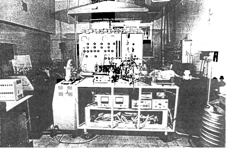
Figure 9. Equipment for air-tightness control of hydro-hinges of BURAN by method of radioactive indicators |
The availability of highly sensitive recording equipment allows to use widely the method directly in conditions of production, and guarantees the radioactive safety.
High responsiveness and accuracy, objectivity and opportunity of control automation are the advantages of RAI method.
The analysis of domestic and foreign experience shows that RAI method is applied for the control of air-tightness of cables, heat exchangers, nuclear reactors, semiconductor devices, mainlines of water pipes, oil- and gas pipelines and pneumatic-hydraulic systems of flying vehicles.
RAI method is used widely enough for the flying vehicle air-tightness control in the USA, France and Japan. The technology of air-tightness control of hydro-hinges and hydraulic hoses with application of RAI method was mastered at NPO MOLNIYA.
In Figure 9, the equipment for air-tightness control of hydro-hinges of BURAN Orbiter is shown.
This equipment provides all necessary technological operations including:
- pumping through internal cavities of a hydraulic system of the stand with the object of tests;
- air removal from the hydraulic system;
- input and dissolution (agitation) of krypton85 radioactive gas in operating fluid;
- creation and maintenance of operating fluid pressure in object of tests in the range 0…21 MPa with a possibility of its adjustment during the conditioning period;
- decontamination of operating fluid, internal volumes of the hydraulic system of RAI stand, auxiliaries and the object of tests;
- temperature and pressure measurement of operating fluid of the object of tests and environment;
- measurement of impulses number (activity) of krypton-85, penetrated through the inspected seals of objects of tests in the space of accumulation at its radio metering;
- measurement of radiation dose at estimation of the degree of dissolution (agitation) of krypton-85 in the operating fluid of the object of tests and at assessment of radiological situation in the zone of works.
The developed technology of the air-tightness control of construction by RAI method with application of this equipment has a sensitivity of 5×10⁻⁸ cm3/s with error of ± 75%.
The described technology has passed the check with the positive outcome at the test of hydro-hinges and hydraulic hoses of BURAN Orbiter in conditions of the different operational factors influence.
Engineers Mr.: Drozdov V.D. (NIAT), Vlasov A.N., S.I.Cherkasov (SMNU113 Volgograd), Deshkin V.B., Stesnyagin A.G. (NPO MOLNIYA) participated in development of this method.
One of the directions of possible application of air-tightness control technology by RAI method is connected to creation and production of cryogenic fuel tanks out of aluminum-lithium alloys and thermoplastic materials.
Further development of RAI method is directed to improvement of design of detecting units of gauging equipment and creation of automated monitoring system of control of construction tightness by RAI method.
Conclusions
The presented methods and monitoring aids of construction air-tightness are tested in the process of creation and production of BURAN Orbiter and have confirmed their practical efficiency. Further development of air-tightness control methods is stipulated by the prospect of reusable aerospace systems and interplanetary spaceships development with the higher requirements on maintenance of their air-tightness.
The technology of air-tightness control of hydraulic-gas units and systems of BURAN Orbiter can be widely used at production of airplanes and helicopters. The techniques of air-tightness control of BURAN Orbiter can find wide-scale application in the national economy.
Nowadays, the development of inter-pipe automated radiometric flaw detector for the control of leakage and stress-corrosion damages of main petroleum pipelines is accomplished for oil and gas industry.
In the field of support of natural environment ecology control, the development of scintillation thin-film automated radiometer for measurement of ultra small values of volumetric activity of radio-nuclides in the gaseous media can be recommended. For recycling branches of agriculture and on their basis the following can be created:
- ultrasonic flow-meters;
- systems of toxic metals mass control;
- high-precision monitoring systems of pressure measurement;
- ultrasonic leak detectors for refrigerating machinery.
Thus, the technological potential accumulated at development of methods and monitoring aids of air-tightness of BURAN Orbiter construction allows to increase the technological level and to receive economic benefit in many sectors of the economy.