
- Documentation
- Table of contents
- AKC
- Introduction
- Airframe Creation
- Technological Problems
- Experimental plant
- Building plant
- Conf. Development
- Aerodynamic Designing
- Algorithms of control
- Guidance & control
- Stand for training
- Training center
- Horizontal flight tests
- Crew on board
- Auto Landing complex
- Structure
- Payload bay
- Metallic material
- Non metallic material
- Non metallic material
- Cabin assembly
- Thermal designing
- Thermal protection
- Heat protection
- Quartz fibre
- Computer designing
- Gas's dynamic
- Strength
- Basic direction
- Tech. preparation
- Technical diagnostics
- Methods & means
- Radio nav. support
- Information & controls
- Control of onboard equ.
- Electric power dist.
- Electromagnetic
- Antennas installation
- Auxiliary power unit
- Hydraulic system
- Cabin
- Safety
- Air transportation
- Automatic landing
- Exp. working out
- Return to space
- SPIRAL
- Analysis of concept
- Horizontal take-off
- BOR-4 & BOR-5
- MAKS multipurpose
- MAKS-D
- Thermal design
- Gas & thermal design
- Wing deflection
- Flight performance
- Maks structure
- Metal materials
- Advanced non metallic
- Information provision
- Onboard starting comp.
- Onboard control comp.
- Control organization
- Aerospace systems
- Economic investigations
- Triplane aircraft
- Technical inventions
- Scientific potential
- Triumph and tragedy
- Birds of a Feather?
- TsAGI wind tunnel
- Bibliography
| -The Mriya is destroyed. |
| -Shipping of Buran-KS to Sotchi. |
| -Antonov is no more. |
| -Buran is now a museum. |
| -New pictures of the blogger Ralph Mirebs. |
From SPIRAL to MAKS
Gas Dynamic and Thermal Design of the Aerospace Planes
Sokolov V.E.
The possibility of using the numerical methods of gas dynamics are considered at designing the space flying vehicles of the SPIRAL, BOR, BURAN and other type to substantiate the temperature scheme, calculation of the non-stationary gas dynamic and thermal flows. The coincidence of the predicted data with the results of the flight tests is shown.
NPO MOLNIYA has wide scientific and technical experience in gas-dynamics of the hypersonic planes earned in the designed bureau of A.I. Mikoyan. This experience has been considerably improved and enhanced thanks to the new scientific and technical ideas and plans realized in the following practical developments. It was forced firstly by the necessity of rapid decisions appeared during the development processes of practical steps and secondly by wide cooperation with scientific organizations of our country. Among them – TsAGI, TsNIImash, NIITP, NII mechanics of the MGU, MFTI and institutes of the Academy of Sciences.
It is worth to mention that experience in gas dynamic and thermal designing and fighter exploitation has been accumulated during the development of BURAN orbiter and perspective aerospace systems. Participation of designers, specialists in gas dynamic and thermal designing was on great demand during the whole development process – goal setting, draft project creation, design drawing issue, experimental development during test flights and in laboratories.
Shortly, it is worth to mention the major works made by the design bureau of A.I. Mikoyan. Without them it was impossible to create and successfully launch BURAN orbital spaceship as well as to conduct project development of aerospace systems.
1. Air inlet design – the complex and thin element of the engine unit of modern jet airplane.
2. Jet nozzle calculation and study for all MIG planes.
3. Practical application of electro-hydrodynamics simulation method - EGDA.2.
4. Mastering of method of characteristics and solution of many practical tasks connected with operative formation of flow fields.
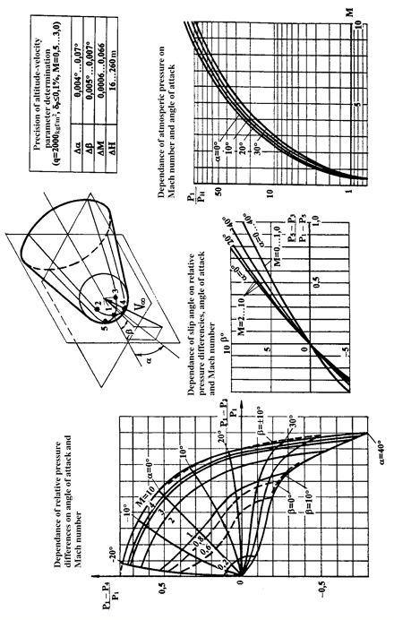
5. Practical application of spatial hypersonic, subsonic and transonic methods of flow field calculation in short term with TsIAM (A.N. Krayko, M.Y. Ivanov) (Figure 1). The application efficiency exceeded all expectations since such calculations provided more volume of hard data with considerable cost reduction of its implementation if comparing with wind tunnel and flight tests. The results of flow fields numerical computing allowed to:
- solve the shaking problem with MiG-25 plane due to displacement of transient compression shock along horizontal empennage surface from unexpanded jet of turbojet engine when it is on supersonic mode;
- eliminate the shaking problem with MiG-35 plane by alteration of diameter of jet nozzle external flaps;
- increase total pressure recovery coefficient on surge inside MIG-23 air inlets by eliminating superstructures flow trace from which falls into air inlets.

|
|
Figure 1. The experimental calculation method for definition of altitude and speed parameters |
During BURAN design and creation the gas dynamics department of NPO MOLNIYA has solved large scientific as well as little engineering tasks which sometimes were so connected between each other that they could be counted at the same time as the first type and as the second one. Let’s see an example.
Temperature Scheme of BURAN
The first produced plane is designed without any normative documents, prepared methods and standards. So one of the most important document is temperature scheme developed during design phase of the orbiter on the basis of wide range of source data:
- on gas dynamics (flow fields after shock waves, boundary layer condition, flow features in stagnation points and areas of separation);
- on surface quality, its structure and chemical properties;
- on internal and external heat exchange;
- on experiment specificity in wind tunnels.
All this complex heap of knowledge, partially contained in different sources, can be divided into three groups of problem solved by the authors of this project for the first time.
Heat flow determination in areas of flow separation (on the upper, ‘shade’ side). The wind tunnel results give considerable overshoot of heat flows if considering that upper surface is the most part of total surface of the orbital plane. That’s why the mistake in determination of heat protection thickness is considerable. The results of wind tunnel tests of different models with various forms and scales as well as results of flight experiments were studied thoroughly. On the basis of analysis of interdependency of basic similarity criteria it was received and experimentally confirmed new criteria dependence between Nusselt number and Mach and Reynolds numbers:
Nu= 1,28 * 10 ^-3 * Re^0.8 /M .
This formula gives for upper surface different dependence of temperature from dimensionless parameters then for lower surfaces.
Experimental Verification of Formulas for Heat Exchange Calculation
Such verification was done on BOR-5 flying model equal to the BURAN orbiter in 1:8 scale. This model fulfilled flight at the same Reynolds number as real orbiter. The solutions of thermal and other problems for this model were also complicated, labor-intensive and non-standard. The model surface temperature was considerably higher then for the orbiter because the model flight was conducted at lower altitudes.
The nose blunt was made of molybdenum alloy working in heat accumulation mode. The calculations of nose thermal conditions were conducted considering into account space-time factors. The measurements made by the thermocouple completely confirmed correctness of Fey-Riddel formula use for stagnation points of the flying vehicle.
The thermal fluxes in the inter-elevon gap of BURAN orbiter were determined on the basis of the BOR-5 flights and heat exchange theory. For that purpose the data about depth of charred layer in materials used in wings and elevon construction was utilized.
Study of radio communication through plasma. When orbiter is flowed by the air plasma part of the atoms lose their electrons and ionized medium prevents radio wave propagation. The gas dynamics department together with NII in mechanics of MGU have calculated electron concentration fields. On the basis of medium radio transparency analysis it was recommended to install antennas depending on the radio communication carrying frequency. Various antenna designs providing radio communication through plasma were suggested. Inventors certificate was issued to the project participants.
Coincidence of Natural Flight Conditions of BURAN Orbiter and BOR-4 Flying Model
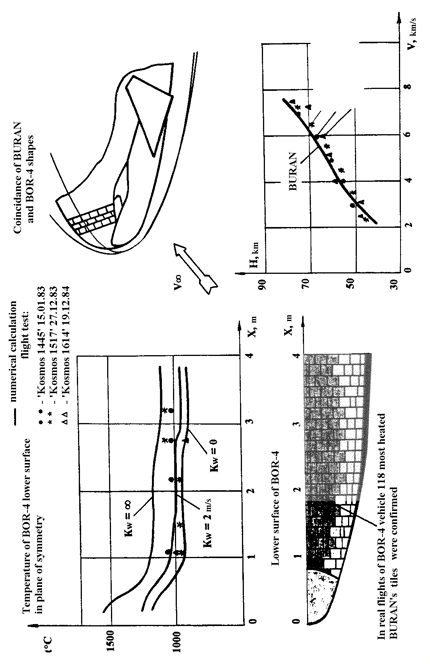
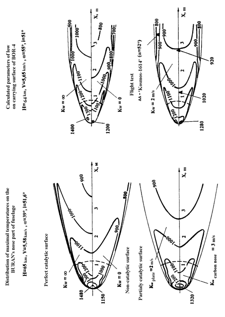
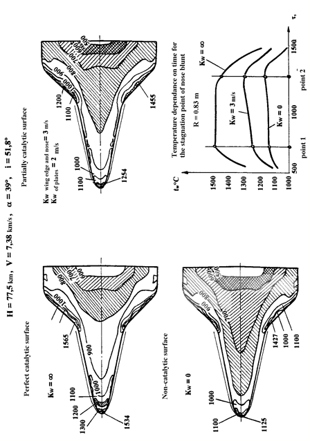
By engineering numerical calculations it was proved complete identity of flight conditions and non-equilibrium flow conditions for the BURAN orbiter and BOR-4 flying model. It is due to identity of their contours in a plane of symmetry, equality of curvature radiuses in stagnation point of nose blunt and equality of specific load (W/S). It was proven also practically identical descending trajectories in H and V coordinates (Figure 2). This could be achieved by bank angle alteration. It guarantees gas dynamic similarity of air plasma parameters, the same distance of shock wave from the body surface, equality of boundary layers and coincidence of physical-chemical processes. By numerical simulation of the BURAN and BOR-4 flight conditions it was proved identity of heat exchange processes, including temperatures, pressures and reaction constants of catalyst recombination (see. figure 3 and 4). Besides, by engineering methods just after first flight it was investigated in details the condition of inter tiles pads. This have permitted basing on the pre-flight measurements of steps between tiles and gaps between them and basing on turbulence theory to define depending on the vehicle length standards for tolerances on steps and gaps between tiles satisfying to the criterion Rek≤110.
From the theory of boundary layer stability it is known dependence of transition to turbulence with roughness Reynolds number Rek calculated according to specific roughness height k and local speed of flow at this height:
Rek= ρ(k) u(k) k / μ(k),
where u(k), ρ(k), μ(k) – respectively longitudinal velocity component, density and viscosity in boundary layer on smooth surface at k distance perpendicular to it.
Speed values were taken from numerical calculations of viscous spatial flow on the lower surface or non-viscous flow with engineering overall estimations of the boundary layer parameters. Three areas of roughness influence on transition location are known:
- roughness doesn’t influence on transition at Reynolds numbers Rek ≤ Rek initial ;
- weak influence area Rek ≤ 110;
- abrupt displacement of transition location upward of flow Rek> 110…180 .
Gas Dynamics Numerical Methods Application in Design Practice
Thanks to consecutive steps made by the general designer G.E. Lozino-Lozinsky for NPO computerization, the gas dynamics department was able to use widely numerical methods in practice. It allowed at initial development phases without waiting wind tunnel test results to issue initial data and to conduct researches of different variants.
The numerical methods were used for creation of temperature and isobaric schemes for the orbiter, analysis of the boundary layer stability, analysis of shock wave loads analysis at surge of AL-31 engine on subsonic analogue of the orbiter BURAN-002- and BURAN liquid rocket engine starting. They also were helpful for analysis of shock waves movement along the airframe surface (it determines tear off possibility of heat protection tiles), analysis of air inflow and outflow from bay when doors are opened, analysis of pilot ejection (the whole complex of problems - from floor folding to cabin loads) and other. It appears from this that it is necessary to know flow field to solve the most part of technical problems connected with flight vehicle designing.
Thus combination of engineering and numerical methods allowed to reduce by 1.6 times load on plug of air-jet engine of the orbiter analogue, to design cabin floor and ceiling, to create scheme of non-stationary loads on heat protection tiles, to determine installation place and angle for sliding of air pressure probe, to calculate tolerance of assembly gap of carbon-carbonic nose cap taking into account its temperature expansion.
Introduced programs and numerical methods allowed to calculate all initial data for designing of system for measuring of barometric altitude, flight airspeed and angles of attack and slide. This system was designed specially for SPIRAL project and was protected by inventors certificate.
The numerical methods require availability of high-qualified specialists and such specialists were prepared.
Determination of Loads on Airframe Skin During its Ventilation in Flight
Engineering practice frequently comes across a task connected with determination of gas flow rate through side hole in adjacent stream. The existing solution in the form of hyper-geometric series in variables of speed hodograph with Chaplygin integral use is not convenient for design engineering practice.

|
|
Figure 2. The experimental calculated validation of BURAN heat protection |

|
|
Figure 3. The experimental-theoretical simulation of spatial viscous shock layer considering physical-chemical processes and catalytic surface properties |

|
|
Figure 4. The temperature distribution on BURAN lower surface considering non-equilibrium physical-chemical processes and catalytic properties of the coating |
Operational experience with computer program EGDA, study of Chaplygin‘s works and engineering practice by means of simplification and assumptions allowed to get empirical dependence between coefficient of gas flow rate through side gap in adjacent stream at subsonic pressure differences and on the basis of Prandl-Mayer task solution about streamline of obtuse angle this dependence was extended to the hypersonic area.
Convenient reference materials for estimator engineer depicted in the form of diagrams of gas flow rate coefficients in the presence of drift speed are absent in literature.
Ventilation folds area of payload bay if considering permissible pressure difference was calculated by means of indicated dependencies. To provide experimental verification of design data required to produce it was manufactured a special box with a hole imitating venting fold. The results of experimental researches confirmed calculated data.
Determination of Mach Number, Angles of Attack, Slip angle and Barometric Altitude
For the BURAN project it was suggested (but not realized because of choosing of Space-Shuttle orbital plane scheme with use of pulled out air pressure probe) the system for determination of altitude and speed parameters by measuring of relative pressure via five holes in the nose blunt of fuselage. During its development programs of gas flow numerical simulation were used. The accuracy of calculations was considerably higher than at pressure measuring in wind tunnels. In that way high performance of designing methods used for decision of practical problems was proved one more time. Simultaneously, it was found out strong influence on pressure distribution of contours of body after nose blunt: form of the cabin and other elements, presence of taper and wedging configurations. It proved that it was impossible to install altitude and speed parameters measuring system without application of gas dynamics numerical methods as one of the major instrument for measuring of flight parameters.
The BURAN orbiter designing on all phases was accompanied by hard calculations which required from specialists participated in the project additional knowledge of adjacent areas of gas dynamics and heat exchange with their numerous branches. It is necessary to indicate great labor, diligence and selflessness of department designers such as V.P. Kryukov, A.P. Kremnev, A.S. Vorobyev, D.G. Vetcheslov, who have gained wide experience for twenty years. It covers gas dynamics and boundary layer numerical methods, thermal fluxes and construction heating calculations. They made considerable contributions into the BURAN creation. These specialists as many others took an active part in development of technical and standard documentation for many types of aerospace planes.
Conclusions
NPO MOLNIYA experience in gas dynamics task solution for aerospace planes and propulsion systems allows to issue all required initial information concerning gas dynamics and thermal loads without conducting of expensive preliminary experiments and wind tunnel tests. Major characteristics of any propulsion systems also can be produced.
The major design documents produced after calculation:
- temperature scheme of maximum thermal loads considering flow separation areas and flow secondary attachment areas;
- layout of pressure distribution along flying vehicle surface considering non-stationary processes;
- layout of internal loadings considering overflow in bays and inflow (outflow) into internal medium with variable in time pressure;
- aerodynamic resistance of aft parts considering liquid resistance of jets and resistance of bottom as a part of total resistance depending on body form factor;
- standardization of cuts, gaps and steps to eliminate laminar-turbulence transition;
- nomographs and methods for determination of Mach number, angles of attack and sliding, barometric altitude for any vehicles;
- recommendations on airframe and its elements geometry, used materials and thermal protection method considering all previous items;
- validation of necessity, adequacy and identity of ground, autonomous and flight test of construction elements in accordance with real conditions of thermal and gas dynamics loads on the most loaded flight stages;
- loads in complicated cases of gas dynamics and thermal loading obtained from jet impulse excitation, surging air blast, liquid rocket engine starting and so on.
The design methods of gas dynamic researches require further development and will take wide application for creation of perspective aerospace system and other flying vehicles.