

- Documentation
- Table of contents
- AKC
- Introduction
- Airframe Creation
- Technological Problems
- Experimental plant
- Building plant
- Conf. Development
- Aerodynamic Designing
- Algorithms of control
- Guidance & control
- Stand for training
- Training center
- Horizontal flight tests
- Crew on board
- Auto Landing complex
- Structure
- Payload bay
- Metallic material
- Non metallic material
- Non metallic material
- Cabin assembly
- Thermal designing
- Thermal protection
- Heat protection
- Quartz fibre
- Computer designing
- Gas's dynamic
- Strength
- Basic direction
- Tech. preparation
- Technical diagnostics
- Methods & means
- Radio nav. support
- Information & controls
- Control of onboard equ.
- Electric power dist.
- Electromagnetic
- Antennas installation
- Auxiliary power unit
- Hydraulic system
- Cabin
- Safety
- Air transportation
- Automatic landing
- Exp. working out
- Return to space
- SPIRAL
- Analysis of concept
- Horizontal take-off
- BOR-4 & BOR-5
- MAKS multipurpose
- MAKS-D
- Thermal design
- Gas & thermal design
- Wing deflection
- Flight performance
- Maks structure
- Metal materials
- Advanced non metallic
- Information provision
- Onboard starting comp.
- Onboard control comp.
- Control organization
- Aerospace systems
- Economic investigations
- Triplane aircraft
- Technical inventions
- Scientific potential
- Triumph and tragedy
- Birds of a Feather?
- TsAGI wind tunnel
- Bibliography
| -The Mriya is destroyed. |
| -Shipping of Buran-KS to Sotchi. |
| -Antonov is no more. |
| -Buran is now a museum. |
| -New pictures of the blogger Ralph Mirebs. |
BURAN Orbital
Spaceship Airframe
Creation
Auxiliary Power Unit of Orbital Spaceship
Dr. Saenko V.I.
There are considered the problems and ways of their solutions, which have arisen during creation of Auxiliary Power Unit (APU), ensuring power supply to the aerodynamic control devices and undercarriage of the BURAN Orbiter.
The necessity of creation of a Auxiliary Power Unit (APU) has arisen practically simultaneously in the USSR and the USA in connection with development of ENERGIA- BURAN and Space Shuttle reusable Space Transport Systems. APU is a power source for drives in control system of aerodynamic control surfaces of the Orbiter at gliding descent and landing.
According to the requirements of BURAN Orbiter reliability, a three-channel hydraulic-circuit system (HS) is applied. One APU is installed in every channel of the system and supplies energy to pumps, creating the working fluid pressure necessary for Orbiter control during the flight. In case of failure of one or two APU-HS channels the logic of control provides consumers switching to the operating channel, which should ensure Orbiter’s safe de-orbit, descent and landing.
The main requirements to APU:
- power output up to 105 kW at gradient of change up to 670 kW/s;
- high level of reliability and firing and explosion safety;
- service life up to 100 flights;
- minimum mass;
- other requirements.
As a result of researches conducted together with leading institutes, the APU gasturbine was selected operating on a propellant and consisting of the rocket-turbo-shaft engine (RTSE), fuel system (FU) and automation unit.
At APU creation a number of technological problems required solution, including:
- selection of energy-efficient fuel;
- creation of optimum design concept, principal diagram of fuel supply and thermostatic control;
- reliable fuel feeding support;
- firing and explosion safety assurance;
- maintenance of reusable application and safety in service;
- development of a complex of techniques and programs of APU research and experimental working-out including the joint APU and hydraulic complex work-out on a fire stand.
In the process of indicated problems solving, the experience of creation of power units for the existing space-rocket systems, and also the available information on similar works on APU for Space Shuttle system was applied.
The following criteria were accepted as the basic at fuel optimization:
- specific consumption;
- fuel toxicity;
- presence of solid phase in products of combustion (decomposition);
- complexity of fuel system servicing;
- other criteria.
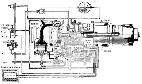
Besides, the possibility of RTSE turnovers regulation by pulse fuel supply was taken into account (Figure 1), which was the most efficient as confirmed by joint researches with TsIAM.
The following fuels were subjected to analysis: oxide + cycline; ammonia (NH3) + nitrous oxide (N2O); peroxide of hydrogen (H2O2) and hydrazine (NH4).
Hydrazine with its decomposition in catalytic reactor was selected as the most completely compliant propellant with the set requirements.
A calculation model was developed for determining the necessary propellant reserve with allowance for the HS channel operating fluid consumption, which is necessary for Orbiter aerodynamic controls drift, losses in HS, and APU power consumption.
The angular positions of rudders’ surfaces were determined on the basis of mathematical simulation of Orbiter descent. The limiting characteristics of HS and RTSE units were taken into account and the calculations were made for the most loaded trajectory.
|
|
Figure 1. Construction diagram of Rocket-Turbo-Shaft Engine (RTSE) |
Selection of APU Design Concept
At selection of the design concept of the Auxiliary Power Unit of BURAN Orbiter, the different versions, including Space Shuttle APU version, were considered. As a result of the analysis the following were accepted:
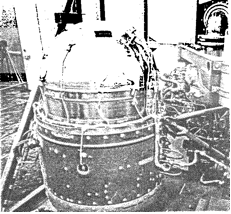
- construction of every APU as two units (RTSE and FU), arranged on the sides of rear fuselage (RF), and automation unit in instrument module of RF (Figure 2);
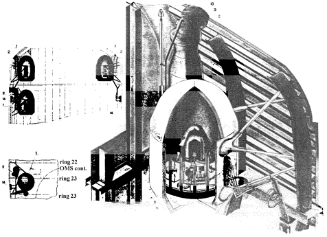
- APU separate arrangement on the sides of RF: 2 - on the left side and 1 - on the right side (Figure 3);
- fixed arrangement of all three APU on board (mounting them is made during Orbiter manufacturing and they are not removed from board during the operation).
Such APU design concept essentially differs from the accepted in Space Shuttle, in which the dislocation of APU units in RF has appeared not too successful.
The application of hydrazine as a propellant requires the maintenance of a temperature mode for all units contacting with it in the range of + 5…50oС during operation.
The main problem, which arose at selection of APU, is that the environment temperature changes in the range from –120 to +160oС. The electrical system, efficient from a point of view of control and mass, with resistor heaters possessing a high scale of reliability in combination with passive means like thermal casing of 25 layers of vacuum insulation and thermal resistors in suspension joints of units was selected.
|
|
Figure 2. APU installed on mechanical frame |
|
|
Figure 3. Installation diagram of APU on board of Orbiter |
At selection of the principal scheme of fuel supply, the attention was focused on the provision of reliability and safety at satisfactory mass characteristics. As a result, the version with displacement scooping was accepted, as the most completely satisfying to the above named requirements at the acceptable mass characteristics.
The principal scheme differs from the scheme of Space Shuttle APU, where the pump supply system ensuring slightly smaller specific propellant consumption, but possessing lower levels of reliability and firing and explosion safety is applied.
The problem of fuel scooping support at all Orbiter flight legs (at the ascent, in an orbit, at descent and landing) has appeared rather complicated because of a wide range of g-loads acting on Orbiter, from weightlessness to +3g along all axes. The existing and advanced systems of feeding, including displacement with soft or rigid separators, centrifugal, inertial, Space Shuttle APU scooping system, etc. For estimation the following criteria were considered: fuel feeding in the engine without gas insertions, minimum mass, reusability and manufacturing features. As a result of a complex estimation, the combined scheme of fuel scooping consisting of a capillary system of fuel scooping in the orbital leg and inertial system with the flexible scoop and recuperator for fuel supply in the phases of launch, descent and landing was offered. The system has successfully passed experimental working-out on stands, on IL-76K flying laboratory and CF-18 centrifuge, has a minimum mass and provides a reusable application.
The problem of firing and explosion safety (FES) was decided in three directions:
- structural measures (welded joints insulating the casing);
- purging the casing by gaseous nitrogen at descent from the altitude of 30 km, at loading and draining;
- observance of the requirements contained in the instructions on handling APU, hydrazine and objects of pressure vessel inspection.
FES system has successfully passed the experimental verification with simulation of hydrazine spill and inflammation. The engineering solution of the problem of FES has been recognized as invention and is protected by the copyright certificate. The ideas laid in FES are perspective and find application in new designs.
Reusability
The existing experience of power units’ application in space-rocket engineering, operating on chemically active propellants does not provide the requirements of reusability, namely:
- carrying out pre-flight, inter-flight and after-flight servicing for minimum time without dismantling from the object;
- removal of the remainders of fuel after flight with reducing the concentration to safe values;
- availability of special-purpose means for carrying out all complex of works on servicing APU in the structure of the object.
Therefore, in the process of APU creation, this problem was decided non-traditionally.
Together with branch institutes, the principal criteria of confirming reusability including the newly developed automatics units were determined. Besides, the problem of removal of the remainders of fuel after flight by a method of thermovacuum cyclical action on internal cavities of APU was solved. The studies and working-out of the complex of equipment and techniques on APU maintenance within the structure of Orbiter without dismantling were accomplished. The conducted experimental tests and works with APU at preparation for the first flight, at enforced delay of flight and after-flight servicing have proved the correctness of accepted solutions and their perspectives for the future development.
Experimental Tests
Confirmation of the requirements, set in Technical Task, at experimental working out is the important stage in creation of a power unit especially of a newly developed. The problem was solved with engaging leading branch research institutes of the country: TsIAM, GIPKh, LII, VIAM, institutes of the customer, etc. As a result of the team’s work, the program of experimental working-out, reliability and safety provision was developed. A lot of unique researches were executed on special facilities:
- impulse system of engine regulation in TsIAM;
- reactor and reusable cycles of fuel loading, draining and decontamination in GIPKh;
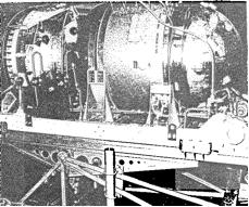
- study on functionality of fuel scooping capillary system under conditions of weightlessness on IL-76K flying laboratory and inertial system of scooping on TsF-18 centrifuge in the Cosmonauts’ Training Center (Figure 4).
|
|
Figure 4. Facility for study on the system of scooping under conditions of weightlessness and alternate g-loads on IL-76K and CF-18 centrifuge |
The firing and explosion safety working-out was conducted with simulation of hydrazine spill at operating APU and with initiation of inflammation with an electric spark, studying the conditions of origin of a tail cone on the exhaust from APU fitting pipe in NIIKHIMMASH, etc.
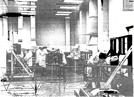
For joint APU equipped with hydraulic complex working out the special installation imitating the flight load of APU was created, which was recognized as invention and protected with the copyright certificate. With the purpose of provision of high quality of APU manufacturing and assembly the special-purpose production (Figure 5) was organized.
|
|
Figure 5. Special-purpose site of APU assembly in pilot production of NPO MOLNIYA |
|
|
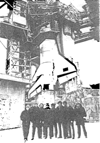
Figure 6. Complex group on APU after pre-launch check on November 13, 1988 |
The majority of the indicated works were performed for the first time in the country, and are of considerable interest for perspective development of power plants for orbiters, airplanes, etc.
The correctness of engineering solutions has been confirmed by results of experimental working out and failure-free operation of all three APU in the first flight of BURAN Orbiter (Figure 6).
The analysis of APU systems and units parameters accomplished after the flight has shown their stability from the delivery production trials to the completion of the flight.
The propellant consumption during the flight was less than the design, which is explained to the fact that the limiting values of the RTSE and HS units’ performances were accepted at calculations.
Conclusions
The accomplished scientific and experimental researches gave the following results:
1. The reusable space power unit of 105 kW, operating on rocket propellant, was created for the first time in the country. It has successfully passed the experimental working-out and trouble-free operated during the first flight of BURAN Orbiter.
2. In the process of APU creation, the following perspective solutions were developed and implemented:
- design concept;
- scheme of service and complex of ground-based equipment ensuring the reusable service of the power unit on the chemically active propellant within the structure of Orbiter;
- reusable combined system of fuel scooping for operation in conditions of weightlessness and exposed to considerable alternating g-loads action.
3. The complex of stands were created, mathematical models, techniques and programs for experimental working-out of the reusable space power unit were developed.
4. The technique of chemically active fuel remainders removal from internal cavities of the fuel system ensuring the required reuse was developed, completed and implemented.
5. The technological problem of power init flight loading simulation is solved at stand working out with the help of the stand-simulator of hydraulic-circuit system operating under the set program.
6. The main objectives of the APU characteristics’ improvement for future development are determined in the direction of profitability and ecological safety increase.
7. The results of development are used in the project of perspective ASTS and can find application at power sources and propulsion systems development of newly created space-rocket systems, airplanes, deep-water vehicles and other articles and systems requiring reliable and compact autonomous power sources.
It is necessary to note that the mentioned problems would have never been solved without engaging the knowledge, experience and talent of many specialists-developers, as: Mr. Fatkov Yu.P. and Ievlev A.V. (NPO MOLNIYA); Marchukov Yu.P. and Syngaevsky A.D. (NPO SATURN); Kartavchenko A.V. and Grigoriev V.M. (GIPKh); Dr. Ogorodnikov D.A., Shestakov K.N. and Gulienko A.N. (TsIAM); Mr. Govarenko G.S. and Moskalenko E.F. (DB ELEKTROPRIBOR); testers Mrs. Roselova V.M. and Gaidukova V.I. (NIIKHIMMASH) and process executives Dr. Bashilov A.S., Mr. Matveikin Yu.V. and Zozulov V.I., without whose initiative and energy no ideas of the designers and many hundreds workers of the indicated organizations would have been implemented.